- Features
-
Key Features
- USB-I2C interface with configurable frequency from 1kHz to 1MHz, wide supply voltage range (2.3V to 5V), multimaster and clock stretching support;
- USB-SPI interface with configurable frequency (up to 4MHz), phase and polarity;
- 32 digital I/O pins with embedded pull-up resistors;
- 8 10-bit analog inputs (ADC);
- 2 PWM outputs;
- 2 32-bit pulse & frequency counters;
- event-driven interface for digital inputs, analog inputs and pulse counters
- 1 status LED and 2 user-configurable LED's;
- no hidden fees: API, updates, software and technical support are free;
- USB 2.0 full-speed (12 MHz) connection to personal computer;
- backward compatible with our well known U2C-12 USB-I2C/SPI/GPIO Interface Adapter;
- RoHS Compliant
General Description
DLN-2 USB-I2C/SPI/GPIO/PWM/ADC adapter is an ideal solution for interfacing your hardware from Windows, Linux or Mac OS X based computer.
The DLN-2 adapter allows you to send and receive data to/from I2C and SPI slave devices at high frequencies, control your hardware using PDM interface and digital outputs and monitor it with digital and analog inputs and pulse counters.
There are a lot of open source examples and ready to use programs that you can download for free from dlnware.com web site. There you can also find comprehensive documentation and examples that show how to interface the DLN-2 adapter from different programming languages.
The DLN-2 interface is available in two modifications:
- the assembled PCB board that you can connect to your hardware with the Diolan accessories;
- the preprogrammed microcontroller (system-on-chip) that you can embed into your hardware.
Event-Driven Interface
One of the most exciting features of DLN-2 USB-I2C/SPI/GPIO/PDW/ADC adapter is an event-driven interface.
You can configure the DLN-2 adapter to notify your application when a specific event occurs. Let’s see that on example. Here is an example.
Let us assume that your application controls a voltage level at some circuit. If the voltage level exceeds 1.6V, it notifies a user about that.
The competitive adapters leave you with the only option to continuously poll the analog input for current value, unreasonably wasting computer resources and USB bandwidth.
The ADC module of the DLN-2 adapter can notify your application when the voltage level exceeds a preconfigured threshold. Your application can set the upper threshold value to 1.6V and continue its regular operation. When the predefined condition occurs, your application will receive an event and notify a user.
The event-driven interface is available for digital inputs, analog inputs and pulse counters.
U2C-12 USB-I2C/SPI/GPIO interface adapter compatibility
Before we developed the DLN-series adapters, we had a U2C-12 USB-I2C adapter that was used by thousands of our customers. After U2C-12 adapter was discontinued, we replaced it with the DLN-2 adapter, which has exactly the same form factor.
The DLN-2 adapter has more extended functionality in comparison with U2C-12 adapter. It supports additional interfaces and higher frequencies. These improvements required from us to change API.
Some of our customers didn’t want to adapt their software to our new API. We put our customers at the center of all we do and we have developed the firmware for DLN-2 USB-I2C adapter that is fully compatible with the previous U2C-12 API. These adapters are available for purchase under part number DLN-2-U2C. For additional details refer to the U2C-12 compatibility article.
- Specifications
-
USB-I2C Interface
The I2C bus frequency of the DLN-2 USB-I2C adapter can be configured in the range between 1kHz and 1MHz. This allows you to connect I2C slave devices that operate in Standard (100 kHz), Fast (400 kHz) and Fast Plus (up to 1 MHz) I2C bus frequency modes.
The DLN-2 interface adapter has two sets of I2C pull-up resistors: 240 Ohm and 1.5 K. You can select which set of pull-up resistors to use with the on-board jumpers. If an external I2C circuit is already equipped with pull-up resistors, you can disable the pull-up resistors that are located on the DLN-2 adapter.
You can connect these pull-up resistors either to the DLN-2 power supply, or to the external power supply. In case you use the DLN-2 power supply, you can select between two options - 3.3V or 5V. The external power supply can vary in the range between 2.3V and 5V.
The DLN-2 USB-I2C interface supports multimaster environment. It can detect if the I2C bus is occupied by another I2C master device.
If your I2C slave device is not able to co-operate with the clock speed given by U2C-12 adapter, it can slow down the communication with clock synchronization (clock-stretching).
DLN-2 supports only I2C master interface. If you need to use I2C slave interface as well, consider switching to DLN-4S adapter.
Symbol Parameter Condition Min Max Freq I2C Bus Frequency configurable 1 kHz 1 MHz PullUp Pull-Up Resistors configurable with solder bridges 240 Ohm 1.5K VIH Input High Voltage 2.31V 5.5V VIL Input Low Voltage -0.3V 0.99V VOHi Output High Voltage Internal VCC 2.9V VOHe Output High Voltage External VCC (VCC-0.4)V VOL Output Low Voltage 0.4V USB-SPI Interface
The SPI bus frequency can be configured in the range between 2kHz and 10 MHz. If you need a faster SPI interface, consider using DLN-4M adapter.
In addition to SPI bus frequency you can also configure the clock polarity (CPOL) and phase (CPHA). DLN-2 USB-SPI Interface supports all 4 SPI bus modes.
DLN-2 adapter operates on 3.3V. However, its SPI interface pins are 5V-tolerant. This allows using DLN-2 adapter with 5V SPI circuits.
DLN-2 adapter can perform half-duplex (read or write) and full-duplex (simultaneous read/write) data transactions.
DLN-2 supports only SPI master interface. If you need SPI slave interface, consider using DLN-4S adapter.
Symbol Parameter Condition Min Max Freq SPI Bus Frequency configurable 2 kHz 10 MHz SS Slave Select Pin 0 5 VIH Input High Voltage 2.31V 5.5V VIL Input Low Voltage -0.5V 0.99V VOH Output High Voltage IOUT= 4.0mA 2.9V VOL Output Low Voltage IOUT= -4.0mA 0.4V USB-GPIO (General Purpose Input / Output) Interface
The DLN-2 adapter has 32 GPIO pins which can be configured as digital inputs or outputs.
Every GPIO pin is equipped with an embedded pull-up resistor. These pull-up resistors are turned on by default to ensure that DLN-2 input pins get the predefined value when no external device is connected.
The DLN-2 adapter stands out against competitive products by its support of event driven interface. With other adapters you would need to continuously poll the GPIO pin for changes, wasting the resources of your PC and USB bandwidth. You can preconfigure the DLN-2 adapter to notify your application (send events) when the input value on the specified GPIO pin is changed.
Symbol Parameter Condition Min Max VIH Input High Voltage 2.31V 5.5V VIL Input Low Voltage -0.5V 0.99V VOH Output High Voltage IOUT= 4.0mA 2.9V VOL Output Low Voltage IOUT= -4.0mA 0.4V IL Input Leakage Current I/O Pin 0.001mA IDC DC Current per I/O Pin 3.0V<VDDIO<3.6V; VOH=2.8V 8mA Absolute Maximum Ratings
Parameter Min Max Storage Temperature -66°C +150°C Ambient Temperature Under Bias -40°C +85°C DC Input Voltage to Any Pin -0.5V +5.5V DC Input Voltage to Pins in ADC mode 0V +3.6V Operating Conditions
Parameter Min Max Ta (Ambient Temperature Under Bias) 0°C +70°C DC Current VCC and GND Pins 50mA - Documentation and Downloads
-
Documentation & Online Support
Development
Title Links Description C/C++ API 
C/C++ API desription. .NET API 
API description for .NET development. LabView Instrument Driver DLN LabView Driver is included in MS Windows dln.3.4.0.exe[zip] setup package Hardware Information
Title Links Description Chip Datasheet LPC1343FBD48 Chip Datasheet Chip pinout DLN-2C chip pinout. Connectors and Jumpers Port and pins assignment on available connectors and jumpers description. Schematics Board schematics. Mechanical Drawing Board mechanical drawing. Software
Title Links Description MS Windows Setup Package 

Contains driver, API libraries, binaries and software examples source code to use DLN adapter in MS Windows OS. Linux Setup Package Contains all required files to start using DLN adapter in Linux. Firmware Update Latest firmware update for DLN adapter. Firmware can be downgraded with this application also. - Reviews
-
Accessories
-
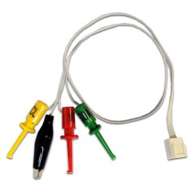
I2C-CABLE-1 I2C Cable with Clips and Crocodile
$9.80 -
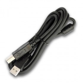
USB-CABLE-1 USB A/B Cable 6 feet
$4.90 -
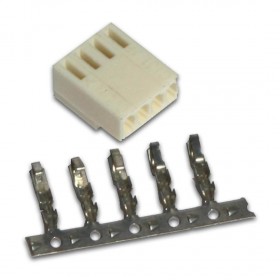
I2C-CONNECTOR-1 I2C Connector (for cable assembly)
$2.80 -
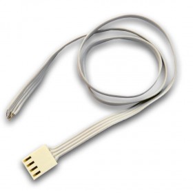
I2C-CABLE-2 I2C Cable with Bare Wires
$7.90 -
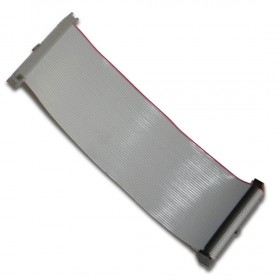
IDC-40-14FF 2x20 Flat Cable, 14 cm, female-female
$8.10 -
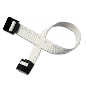
IDC-10-20FF 2x5 Flat Cable, 20 cm, female-femail
$5.90 -
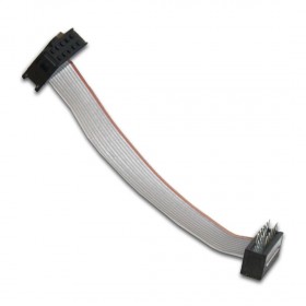
IDC-10-7FM 2x5 Flat Cable, 7 cm, female-male
$5.70